| Author |
Message |
|
Joolz
Firing on two.
Joined: January 5th, 2009, 5:48 am
Posts: 1687
Location: Haven't a clue

|
 Re: Joolz's Red One I was thinking more that the uneven voltage reading was a bad connection in the probe leads as the reading was sometimes well under 12volt. But I tried measuring the voltage at the alt with the only analogue meter we've got here, but with the dial only being 5cm across, reading the 0-50v scale, and trying to hold both probes and the meter with one hand while 'blipping' the throttle with the other, then I'm not really sure I could tell the difference between 13.5 and 14. Actually I'll try again with some help. The blockdiodes/rectifier diodes/bridge are all the same thing, yes? The three round things pressed into the top plate, and more underneath? They don't look easy to change, they're all crimped connections. But these were changed with the alternator, it's unlikely that they had the same fault in both alternators. 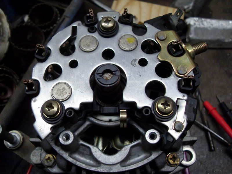
_________________

|
| November 21st, 2012, 12:58 am |

|
|
|
lpgo
Firing on 1-2 Spark
Joined: November 8th, 2009, 5:42 pm
Posts: 2847
Location: NL
|
Re: Joolz's Red One The blockdiodes/rectifier diodes/bridge..... There must be 4 of them, but I think they are in the regulater thing not in the alternator... circuit like this Attachment:
 blokdiodes.jpg [ 3.89 KiB | Viewed 3879 times ]
this makes from the dc (current) (alternator) ===> (ac current) (battery)
_________________
Russell wrote: Hi Geo,
you've been one of the sites biggest attractions in recent years.
Russ
|
| November 21st, 2012, 1:07 am |

|
|
|
Joolz
Firing on two.
Joined: January 5th, 2009, 5:48 am
Posts: 1687
Location: Haven't a clue
|
Re: Joolz's Red One Thanks Lpgo, I know the basic bridge rectifier, but if those discs are the diodes, and I'm sure they are http://www.ebay.co.uk/itm/BOSCH-ALTERNA ... 483e7cf901, then there are at least 6 of them, I think this is because there is more than 1 winding giving output, sort of like 3-phase or something. There are also I think the same number of smaller diodes hidden under the plate, they stop the power from the warning lamp flowing into the coils.
_________________
Last edited by Joolz on November 21st, 2012, 1:34 am, edited 1 time in total.
|
| November 21st, 2012, 1:30 am |
|
|
|
Joolz
Firing on two.
Joined: January 5th, 2009, 5:48 am
Posts: 1687
Location: Haven't a clue
|
Re: Joolz's Red One I've looked at the regulator and brushes to see if I could understand how it works, this alternator is the type which works with only one wire, it does not need external power for the field windings. The small spade connector is from the warning light. It did occur to me that I've recently changed the warning light for an LED and I wondered if perhaps it relied on a certain level of current flowing from the light that it isn't now getting. I tried disconnecting the wire on that spade, no difference. I think this is how it is connected up, it's hard to tell exactly what's going on under the plate with the diodes in. 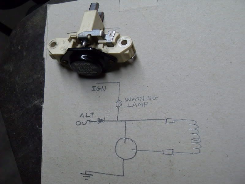 The large circle is the round black regulator object. I was wondering if it would work if I removed this and connected the brushes up to the 2cv's remote regulator. At the moment I can't see why not.
_________________
|
| November 21st, 2012, 1:31 am |
|
|
|
Diesel Dave
2CV Fan
Joined: October 31st, 2012, 5:31 pm
Posts: 79
|
Re: Joolz's Red One You do need it to be a bulb and it does need to be connected otherwise it won't charge. I can't remember the reason myself but I pinched the following from a VW site: It is absolutely essential that the (D+) terminal on the alternator be connected to a functioning "Alt" warning light in the instrument cluster. If this light is missing or defective, the alternator will NOT charge the battery! See my hand-drawn wiring diagram above. Also see Speedy Jim's diagram, which is much better than mine! The system is very simple, but it's absolutely critical that you get it right. The (D+) terminal on the alternator MUST connect to a functioning warning light in the instrument cluster. There should be just one wire (blue) from the (D+) connector on the alternator to the button on the bottom of the normal indicator light in the dash. The dash light is also wired from the (D+) (Blue) to ignition terminal #15 on the coil, which in turn is connected to the positive (+) post on the battery (Black). There is no ground wire on the light; the body of the bulb is connected to ground via the light holder (which also provides the ground connection for the other dash lights as well.) The three bulbs (ALT/OIL/TURN) all have a common connection in the socket which goes to ignition terminal #15 on the coil (which receives power from the (+) post on the battery by way of the ignition switch). The alternator must get a feedback current through the "Alt" lamp in the instrument cluster so it can sense the battery voltage; it uses that as part of the alternator's internal circuitry needed to charge the battery. In other words, with the ignition on but engine off, the indicator light sees 12 volts from the battery (via ignition terminal #15 on the coil) and glows, but with the engine running, it sees 2 volts (14 volts minus 12 volts) running the other way, from the alternator. It doesn't glow (needing more than 2 volts to do that), but the alternator still "sees" the connection to the battery. So -- If the Alternator is charging, the (D+) terminal has 12 volts on it; the blue wire from (D+) carries 14 volts to the "Alt" light in the instrument cluster. When the engine is running, there is 12 volts on the *other* side of the lamp from ignition terminal #15, so potential difference is only 2 volts and the bulb doesn't light. But, if the alternator dies or the drive belt breaks, there is no voltage on (D+) (looks like ground) and current flows from #15 thru the lamp to (D+), and the "Alt" lamp comes on to warn the driver of a problem. An LED light won't work for this purpose. LED's are diodes and will not allow current to flow in the opposite direction. With the LED, it would see the 12 volts, but the reverse flow 2 volts would be stopped by the diode nature of the LED, so that wouldn't work. The 12-volt 2-watt indicator bulbs are available at any VW parts store. The same bulb is used for the speedometer illumination bulbs (two of them) and the other indicator bulbs in the instrument cluster. In a pinch you can borrow one of the illumination bulbs to replace a blown Alt indicator bulb -- the speedometer will be a bit dim on one side but can still be seen until you get a replacement bulb. Linky: http://www.vw-resource.com/alternator_wiring.html#alt
|
| November 21st, 2012, 1:41 am |
|
|
|
Joolz
Firing on two.
Joined: January 5th, 2009, 5:48 am
Posts: 1687
Location: Haven't a clue
|
Re: Joolz's Red One Thanks for the input Dave but that doesn't seem at all right to me, firstly; Joolz wrote: The small spade connector is from the warning light. It did occur to me that I've recently changed the warning light for an LED and I wondered if perhaps it relied on a certain level of current flowing from the light that it isn't now getting. I tried disconnecting the wire on that spade, no difference.(ie still charging as much as before) I can only assume that that is for a different system. It says that the D+ terminal provides the power for the warning lamp and is also connected to the ignition feed, and that the bulb earths through the casing, none of which bares any similarity to the set-up in my car. I can't help thinking it's either very badly described, or just plain bollocks! The bit about 14volts and 12volts both existing in different parts of the circuit at the same time!!  No, however many times I read that I can't get it to make any sense, I'm 99% sure it's all complete nonsense, and written by someone who believes wires have smoke running through them. I'll not say so out loud though, in case Ken comes along and tells me it's correct. 
_________________
|
| November 21st, 2012, 2:11 am |
|
|
|
ken
Agony Aunt - You have a car problem? Speak to Ken
Joined: March 6th, 2009, 1:40 am
Posts: 3675
|
Re: Joolz's Red One Google search keywords; alternator + warning + light + resistor + parallel + ohms = http://jenniskens.livedsl.nl/Technical/ ... Tip090.htmAny good?
_________________

|
| November 21st, 2012, 2:47 am |
|
|
|
Joolz
Firing on two.
Joined: January 5th, 2009, 5:48 am
Posts: 1687
Location: Haven't a clue
|
Re: Joolz's Red One Very good Ken, but the extremely precise choice of search words makes me think you knew that already. I'm quite pleased that it confirms my sketch.
It does seem to be a common consensus that an LED needs to have a resistor fitted in parrallel in order to work, but there are still a couple of unanswered questions for me. Firstly once up and running it should be self-exciting, and surely as it gets up to 14v with no load on it then it's managing to get started. Once in operating mode, (the first of the 2 pics in your link), the lamp plays no part.
I've also just remembered that since fitting the LED it takes longer for the light to go out after the engine is started, so that does actually back up the infomation about the lamp's role. But importantly the light does then go off.
Secondly why is it only failing to work when it's got a load on it, and then it's only dropping half a volt, not cutting out completely.
Another very small but 'interesting feature' is that the warning light glows very slightly all the time when the engine is running, it's so faint that it can only be seen at night, but there must still be a very small voltage difference across it. Will an LED emit any light when the voltage is reversed, as the route to it's positive side is more convoluted and more likely to have some resistance which is dropping voltage.
And I still wonder if I could bin the 'round black thing' aka Laderegler(charge controller/regulator) and connect the DF wire to the output from the standard 2cv regulator, which should give me the 14.4volts I'd like. The warning light could be left as it is without a parallel resistor, and should still function.
Whatever, next thing to do is either try putting a resistor in parallel, or swapping back to conventional bulb, depending on what I can find, and see if that fixes the issue.
_________________
|
| November 21st, 2012, 4:06 am |
|
|
|
Luke
Firing on two.
Joined: December 9th, 2008, 7:50 pm
Posts: 662
|
Re: Joolz's Red One I must confess it's too early for me to have read all of the above, but I *seem* to recall that you can get away with connecting the exciter feed straight to the battery. The bulb (connected in series between the battery and the exciter terminal) is just a handy indicator that there is current flowing along that wire. Once the output voltage of the alternator reaches the battery voltage, the current stops flowing and the light goes out. Conversely, I suppose if the connection between the alternator and the battery was ever broken, the current would flow the other way and the bulb would light up again.
I'm afraid I can't explain why it works some of the time either, but why not try connecting that terminal straight to the battery, for testing purposes. If you're loathed to trust my shaky memory, you could include a bulb, which obviously would give you a bit more idea of what's going on anyway.
Oh, and my cheap and cheerful multimeter seems to be next to useless inside most engine bays with the engine running. I've always assumed it was down to less than perfect HT suppression and rubbish shielding inside the meter...
|
| November 21st, 2012, 8:14 am |
|
|
|
ken
Agony Aunt - You have a car problem? Speak to Ken
Joined: March 6th, 2009, 1:40 am
Posts: 3675
|
Re: Joolz's Red One Joolz, this looks promising, particularly the last paragraph... http://www.pelicanparts.com/techarticle ... eshoot.htm
_________________
|
| November 21st, 2012, 1:09 pm |
|
|
Who is online |
Users browsing this forum: No registered users and 35 guests |
|
You cannot post new topics in this forum
You cannot reply to topics in this forum
You cannot edit your posts in this forum
You cannot delete your posts in this forum
You cannot post attachments in this forum
|
|