International2cvFriends.com
http://www.international2cvfriends.com/forum/

Joolz's Red One
http://www.international2cvfriends.com/forum/viewtopic.php?f=5&t=137
Page 3 of 54

Author:  Joolz [ March 29th, 2009, 2:25 am ]
Post subject:  Re: Joolz's Red One

I've capped the ends now and smoothed off the edges, so they're not exactly sharp. Plus I'm unlikely to hit someone while traveling sideways, it's not impossible, just unlikely.

Author:  Russell [ March 29th, 2009, 11:33 am ]
Post subject:  Re: Joolz's Red One

I like what you've done, I was thinking of doing something similar which also followed the line around the bonnet aswell, as and when I get round to it...

Author:  ken [ March 29th, 2009, 3:31 pm ]
Post subject:  Re: Joolz's Red One

Joolz,
?
Guess I wasn't clear enough, if you managed to interpret my comment as suggesting that your bumper might be a danger to pedestrians or other road users.
What I was referring to was the probability of injury from those 'eversharp' ends of a Dyane stainless bumper when carrying out any job requiring removal of the front wings, such as kingpins or front wheel bearings.
After the first time, I learnt to always cover the bumper ends... ;)
Ken.


Joolz wrote:
Plus I'm unlikely to hit someone while traveling sideways, it's not impossible, just unlikely.

Author:  Joolz [ April 3rd, 2009, 11:09 am ]
Post subject:  Re: Joolz's Red One

You're right Ken, having never caught my ankles on the bumper that point was lost on me, I didn't leave the previous bumper on long enough. Thinking about it, if your bumper's at the 'correct' height then steel toecaps should be enough to prevent injury.
I have, however, learnt to hang a thick rag over the ends before removing the wings to stop the paint from getting scratched.

Author:  Joolz [ July 4th, 2009, 1:58 am ]
Post subject:  Re: Joolz's Red One

Three months later, I've been doing something, I've made meself a 'parcel shelf'. It's 3/4" MDF, a bit heavy but it came at a good price, I scrounged it off the parents. The mountings are the results of many hours head scratching, a couple of other bracket setups were abandoned when they were nearly finished and I still think the fronts could have been slightly different.
Image

Image
I can't help thinking that second pic looks like a comedy spoiler someone accidentally mounted inside the car.

Right, just cut some bloody great holes in it now,
Image
That should do. No I didn't cut the holes with that saw, I used a coping saw, for those that don't know it's not electric.

And finally a bit of black paint and cover it with carpet, jobs a good'un, sweet, if I do say so myself 8-) :lol:
Image
Image

Author:  Joolz [ July 4th, 2009, 2:04 am ]
Post subject:  Re: Joolz's Red One

In the unlikely event that anyone's wondering what the bumper looks like now it's finished and fitted, it isn't, on either count :oops: soon though.

Author:  Neil [ July 4th, 2009, 2:16 am ]
Post subject:  Re: Joolz's Red One

that looks tres smart monsieur

Author:  Jonathan [ July 4th, 2009, 6:53 pm ]
Post subject:  Re: Joolz's Red One

Very clever way of fitting it to the car, I like it 8-)

Author:  Joolz [ January 18th, 2010, 10:49 pm ]
Post subject:  Joolz's fuse box mods

Some time ago, on some other random thread, I may have mentioned something about upgrading the fusebox and adding some extra fuses and writing it up here when I had. Well about 6 months after completing the job, here it is.

I wanted to add some extra fuses to my car's electrical system as it was a little to basic for my liking. The first extra fuse was to protect the accessories circuit(radio and cig lighter). It would have been quite easy take wires straight from the battery and use inline fuse holders, but I hate the look of that, it always looks like such a bodge

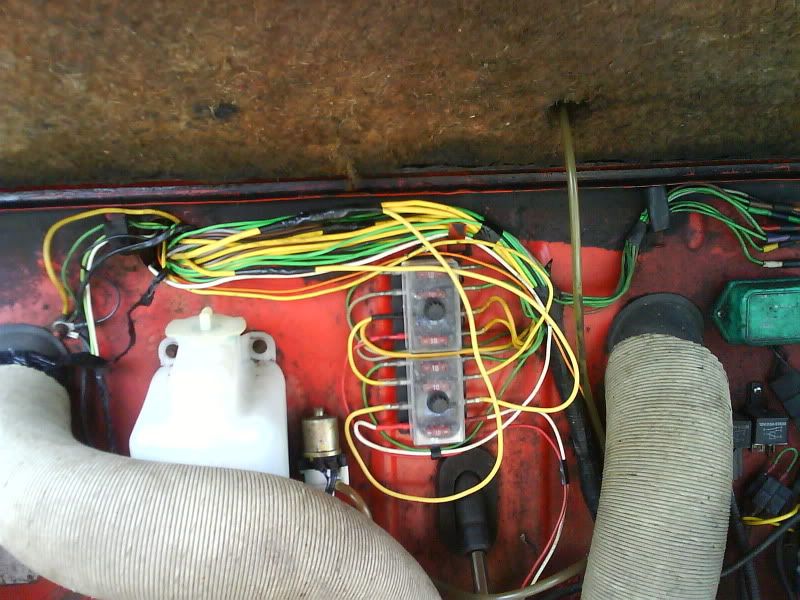
My car, being a late model, came with 2 fuse boxes as standard, the second of which has 3 empty spaces. The original idea was to get hold of some extra fuse holder terminals and make use of the extra places, but being unable to find new terminals and accepting that the citroen fusebox is not the most reliable thing in the world, I realised that buying an aftermarket spade fusebox was the sensible way forward. My local motorfactors provided one of these;

Image

Mounting it on the bulkhead in place of the originals was pretty straight forward, I then cut the wires off the original boxes and joined them to the new box one at a time, so as not to mix any up. Keeping the same order as citroen had intended to make any future fault finding easier.

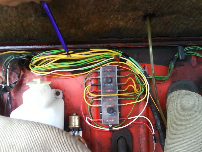
I'll try an explain where I deviated from standard. Counting down from the top, number 3 fuse is 'live with ignition'. You'll notice in the pic that it has 2 wires on the left hand end, one is the normal feed from the ignition switch, the second is a feed to fuse 6. Fuse 6 supplies the windscreen wipers, I wanted them to have their own fuse so that if the linkage ever jammed, hopefully blowing the fuse, then nothing else would be disabled.

Fuse 4 is the 'permanent live' fuse, and is fed from the right hand end (all other fuses are fed from the left, left and right are as you look at the picture). Although difficult to see, there are 2 wires on the output side, the partially hidden standard grey wire and a second red wire, the latter is for the stereo and a clock.

Fuse 7 is for the supply to the lighting switch, more of which later.

Fuse 8, with the white wires, is an accessories fuse, it's from the first position of the 4 position ign switch and supplies the stereo and in future a cig lighter.

Image

There's one more wire to add at some point in the future, I forgot at the time, and thats from the right sidelight fuse (the top one if I remember rightly). This would be to light up some extra gauges which aren't fitted yet anyway.

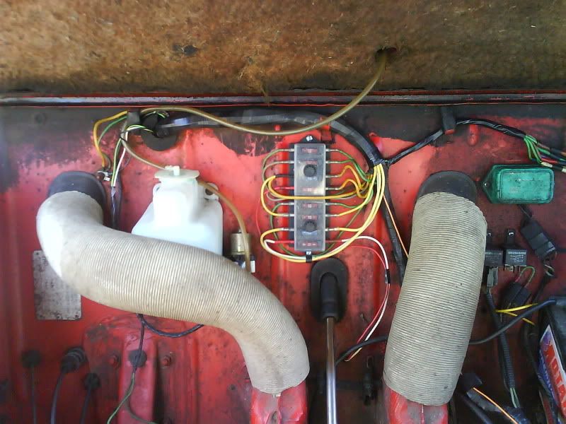
Also partly visible in that pic is the electric washer pump, recycled from a fiat strada.

Author:  Joolz [ January 18th, 2010, 10:55 pm ]
Post subject:  Re: Joolz's Red One

In order to fit a fuse into the feed for the lighting switch, I needed to find where it branched off the main power supply. A combination of removing the speedo panel and unwrapping the loom revealed this crimped connecter joining four yellow wires, these wires are;
fat wire on the right - from starter and alternator,
thinner wire on the right - to permanent live fuse,
fat wire on the left - to ignition switch,
thinner wire on the left - to lighting switch.

Image

The light supply wire was cut about 25mm from the connecter and extensions soldered to either end to route it via the 15amp fuse.

Image

Page 3 of 54 All times are UTC + 1 hour [ DST ]
Powered by phpBB © 2000, 2002, 2005, 2007 phpBB Group
http://www.phpbb.com/